How to select brush machine?
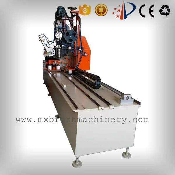
Do you need a tufting machine or a drilling&tufting machine?
In terms of function, there are two designs for brush machine. When you choose different designs, corresponding molds are required to make the base.
Single tufting machine, the machine only fill filament(fiber, bristle, hair) into the base.
Moulds with holes, base with holes.
Tufting machine is a good choice at the business beginning, enter the market and test the product with less investment.
Drilling and tufting machine, the machine drills holes and fill filament into the base at the same time.
Moulds without holes, base without holes.
It has stronger stablility and functionality. When business comes to mature stage, customer tends to consider it with a long term vision. It helps avoiding high cost and uncertain life span problems of moulds.